

- OVER DRIVE (5th GEAR) LOCK OUT SWITCH
- INSTALLATION INSTRUCTIONS
- 2001 – 2002 6.6L DURAMAX DIESEL WITH
- ALLISON 1000 SERIES 5 SPEED
- AUTOMATIC TRANSMISSION (RPO CODE M74)
- MITTIE M. DRAGOSLJVICH 11/12/2002
- CONCERN & SOLUTION
Owner’s of 2001 – 2002 6.6L Duramax diesel equipped vehicles with the Allison 1000 series 5 speed automatic transmission (RPO code M74) may experience “shift busyness” or frequent shifting between 4th and 5th gears while operating the vehicle under heavy loads or during towing. Since the gear indicator on these vehicles lacks a 4th gear selection, it is not possible to manually select 4th gear. A TCM (Transmission Control Module) calibration software update was made available by GM on 03/24/2002 to address this concern. The updated TCM calibration contains a feature to disable 5th gear (overdrive) operation. To enable the OD lockout feature, terminals must be added to the TCM C1 connector and a momentary Over Drive Lock Out (ODLO) switch must be installed as described by the following procedure.
Caution should be used whenever turning ON or OFF the Over Drive Lock Out (ODLO) feature to prevent unexpected transmission shifting that could lead to loss of vehicle control resulting in an accident, property damage, serious injury or death.
PARTS NEEDED
- The TCM must have the updated TCM calibration software installed for the ODLO feature to function. The updated TCM calibration software was available from GM after 03/24/2002.
- (2) Terminals GM part #12084913 (5 per package) or GM part #12084912 (10 per package) to add to the TCM at terminal positions C1-12 and C1-28 for the Over Drive Lock Out (ODLO) momentary switch.
- (1) Terminal GM part #12084913 (5 per package) or GM part #12084912 (10 per package) to add to the TCM at terminal position C1-20 if an Over Drive Lock Out (ODLO) indicator LED is desired (optional).
- (2) Lengths of wire for the ODLO switch (approximately 15 feet each, 18 or 20-gauge). Two additional lengths of wire will be needed if the optional LED indicator is desired. The length of wire needed will be dependent on the location of the ODLO switch and LED indicator. The smaller 20-gauge wire is easier to work with and to add the terminals to the TCM. Using different color wires will aid identifying the wires during installation.
- (1) Momentary switch.
- (1) LED and (1) 10K ohm resistor (wired in series) if the optional LED indicator is desired. The ohm value of the resistor will vary depending on the type and voltage of the LED used. Radio Shack sells a LED with attached resistor that works well in this application (part# 276-0271 GREEN or part# 276-0270 ORANGE, these part numbers may appear as 276-271 or 276-270).
- Crimp tool and connectors to attach the wires to your momentary switch. If installing the optional LED indicator, a fuse tap, 1A or 2A fuse, and fuse holder will be needed. Soldered on connectors may be used instead of crimp on connectors.
- Split loom tubing, electrical tape, cable ties etc. as needed to clean up the appearance of the installation.
- A small amount of dielectric grease may be used on the added terminals for moisture resistance.
- Access to the factory shop manuals is recommended if unexpected questions or problems arise during the installation. The GM factory shop manuals can be purchased online from Helm Inc. at www.helminc.com
- A multimeter will aid in installation, but is not required.
ODLO SWITCH INSTALL
- Disconnect both batteries by unbolting the GROUND or NEGATIVE (-) cable from each battery.
IMPORTANT: The ignition switch must be OFF when removing or reattaching the battery cables or damage to the ECM and/or TCM is possible. - Locate the Transmission Control Module (TCM). The TCM is located on the driver’s side (DS) of the engine compartment (see FIGURES 1 and 2)
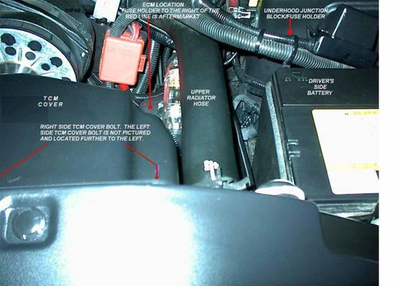
FIGURE 1: ECM and TCM LOCATION (Driver’s side of engine compartment 2001 Duramax Diesel)
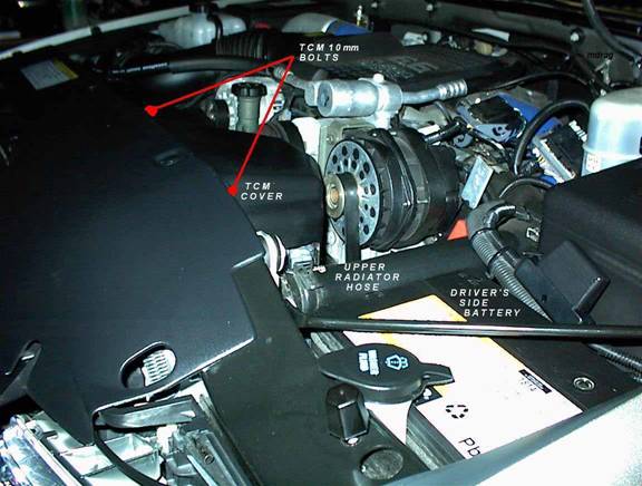
FIGURE 2: TCM LOCATION (Driver’s side of engine compartment 2001 Duramax Diesel)
- The TCM is attached to the radiator shroud by two 10 mm bolts. Remove the two 10 mm bolts along the top edge of the radiator shroud and unplug the (2) TCM connectors from the TCM. The TCM will remain attached to the cover. Lift up and remove the TCM/TCM cover and place them in a safe location to avoid damage. Handle the TCM carefully and avoid dropping it to prevent damage.
- Identify the C1 TCM connector. The C1 connector is GRAY in color and has a CLEAR cover over the terminals. C2 is the other TCM connector, and is RED with a RED cover.
- Release the tabs on the wire side of the gray C1 connector with the CLEAR cover over the terminals for access to the back of the connector.
- There are small numbers printed on the TCM connector body to identify the terminal positions. Locate TCM terminal positions C1-12 and C1-28 for the ODLO switch, and position C1-20 for the optional LED indicator. Place small marks on the TCM C1 connector to facilitate identification of these positions during terminal insertion.
- Prepare the terminals (GM part #12084913 or #12084912) that will be added to the TCM C1 connector by crimping or soldering the terminals to 18 or 20-gauge wire of sufficient length to reach the location of your switch and LED indicator. Using smaller 20-gauge wire will make adding the terminals to the TCM C1 connector easier. Different color wire should be used for each terminal to aid identification. If soldering terminals to the wire, use solder sparingly and avoid clumping the solder since it will be difficult to properly seat the terminals in the connector body. Apply a small amount of dielectric grease to the terminals for moisture resistance.
- Using a small pick or other sharp object, puncture the insulation from the wire side of the TCM C1 connector to correspond to the position of the terminals you are adding (terminals at positions C1-12 and C1-28 for the switch, and C1-20 for the LED indicator).
- Remove the CLEAR cover over the terminal ends of the C1 TCM connector by releasing the tabs on each end.
- Insert the terminals you prepared above (with wire attached) from the wire side of the TCM C1 connector. Be sure to properly position the added terminals in their desired locations. Record the wire color/terminal position for the terminals you add for later reference.
- VERY IMPORTANT: Make sure that the added terminals go all the way to the edge of the TCM C1 connector to insure proper contact. Use the existing terminals as a guide.
- Replace the CLEAR cover over the terminal ends and reassemble the cover over the wire end of the C1 TCM connector. Carefully inspect the reassembled TCM C1 connector to make sure all terminals are in the proper location.
- Route your added wires as desired toward the firewall. Use split loom tubing, electrical tape, and cable ties as needed for an OEM appearance.
- Reattach the TCM to the proper location using the two 10 mm bolts. Remember to plug in the (2) TCM connectors. The wire harness on the two TCM connectors are different lengths to aid in proper placement.
- Find a place on the firewall to run the added wires into the cab. On the Duramax diesel, a good location is pictured below:
FIGURE 3: FIREWALL ACCESS FOR WIRING (2001 Duramax Diesel)
You can also pierce the rubber boot for the main wire harness entry into the cab located below the hydroboost assembly and run the wires into the cab.
- Find a suitable location in the cab to mount the ODLO momentary switch.
- Connect the wire from TCM terminal position C1-12 to one pole of the momentary ODLO switch.
- Connect the wire from TCM terminal position C1-28 to the other pole of the momentary ODLO switch.
- If installing the optional indicator LED, a resistor must be attached to either the positive or negative side of the LED. Note: The ohm value of the required resistor will vary with the type and voltage of LED used. GM recommends a 10K ohm resistor. Radio Shack sells a LED with attached resistor that works well for this application (part# 276-0271 GREEN or part# 276-0270 ORANGE, these part numbers may appear as 276-271 or 276-270).
- Attach the wire from TCM terminal position C1-20 to the negative leg of the LED. The negative leg of the LED is usually shorter in length compared to the positive leg. TCM terminal position C1-20 provides a ground circuit whenever ODLO is engaged.
- Locate a switched 12V source. A fuse tap can be used to obtain switched 12V power from the fuse panel accessible when the driver front door is opened. It is recommended to use an in-line fuse (1A or 2A) on this 12V power lead as a precaution.
- Route the 12V power lead to the LED indicator light, and attach to the positive leg of the LED. The positive leg of the LED is usually longer than the negative leg.
- Double-check all wiring and connections. Make sure the wires do not interfere with the normal operation of any vehicle components, and will not be pinched or crushed.
- Reattach the battery cables. IMPORTANT: The ignition switch must be OFF when removing or reattaching the battery cables or damage to the ECM and/or TCM is possible.
ODLO SWITCH OPERATION
Caution should be used whenever turning ON or OFF the Over Drive Lock Out (ODLO) feature to prevent unexpected transmission shifting that could lead to loss of vehicle control resulting in an accident, serious injury or death, and property damage.
- If the vehicle operator determines that it is desirable to maintain 4th gear and prevent the Allison 1000 series automatic transmission from shifting into 5th gear (overdrive), activate the ODLO feature by pressing the momentary ODLO switch. This will prevent the Allison 1000 series transmission from shifting into 5th gear. A second press of the momentary ODLO switch will disable the ODLO feature and allow the transmission to complete the 4th to 5th gear up shift when needed.
- If the ODLO switch is activated while in 5th gear, the Allison 1000 series transmission will down shift to 4th gear and prevent further 4th to 5th shifting. A second engagement of the ODLO switch will defeat the ODLO feature and allow normal 4th to 5th shifting.
- The ODLO function can be selected or disabled at any time. It may take a few seconds after starting the engine for the ODLO circuit to activate. Caution should be used whenever turning ON or OFF the Over Drive Lock Out (ODLO) feature to prevent unexpected transmission shifting that could lead to loss of vehicle control. Loss of vehicle control can result in an accident with serious personal injury, serious injury to others, or death. Damage to your vehicle, other vehicles, trailer, or cargo is also possible.
- If the optional indicator LED was installed, the LED will light when pressing the ODLO switch to activate the ODLO feature. A second press of the ODLO switch will disable the ODLO function and turn off the indicator LED.
- The Over Drive Lock Out feature defaults to OFF each time the vehicle’s ignition key is turned off. Therefore, the ODLO feature is OFF every time the engine is started and the ODLO momentary switch must be pressed to activate the feature.