

Fast Idle Installation Instructions for LB7 Duramax
2001 – 2003 6.6L LB7 DURAMAX DIESEL WITH
FACTORY CRUISE CONTROL*
- MITTIE M. DRAGOSLJVICH
- INITIAL VERSION: 11/12/2002
- UPDATE: 02/15/2003
*IMPORTANT: THE FACTORY CRUISE CONTROL OPTION MUST BE PRESENT FOR THE HIGH IDLE SWITCH TO FUNCTION. PLEASE READ ALL OF THE INSTRUCTIONS BEFORE PROCEDING. IF THE CRUISE CONTROL OPTION IS NOT PRESENT, THE HIGH IDLE SWITCH MAY NOT FUNCTION, OR ONLY THE STANDBY SPEED WILL BE AVAILABLE. AN ADDITIONAL SWITCH OR SWITCHES FOR THE CRUISE CONTROL CIRCUIT MAY BE NEEDED. PLEASE READ THE SPECIAL CONSIDERATIONS CONCERNING THE PTO CONNECTOR.
SPECIAL CONSIDERATIONS
- Poor drivability will result if the high idle switch is left on when driving. The Duramax will accelerate poorly above ~ 2200 RPM.
- The 2001 Duramax equipped trucks have three high idle speeds: STANDBY ~850 RPM, SET ~1250 RPM, and RESUME ~1700 RPM. The 2002 and 2003 trucks have only the SET and RESUME speeds available.
- In some cases, the high idle option may need to be programmed using a Tech2 diagnostic scanner before it will function.
- The STANDBY, SET, and RESUME RPM speeds can be changed using the Tech2 diagnostic scanner.
- A ‘variable speed’ option exists for PTO/high idle operation and is visible with the Tech2 scanner. Attempts at programming the variable speed option on the 2001 and 2003 Duramax equipped pick-ups have been met with limited success. The variable speed option allows the user to ‘tap up’ or ‘tap down’ the idle speed in 100 RPM increments using the RESUME (tap up) or SET (tap down) buttons on the cruise control.
- The variable speed option is available on the 3500 chassis cab models with the factory RPO codes M1F and PTO. A modified floor pan is part of those options. RPO codes M1F and PTO are unavailable on the 2001 – 2003 2500HD/3500 pick-up platform due to clearance issues with the floor pan used on these trucks.
- Some of the 2500HD/3500 trucks have been manufactured with the PTO connector in place. The PTO connector (if present) should be located behind the airbag disable switch or behind the glove box on the passenger side. It is described as an 8-position connector taped up in one of the above locations.
- If the PTO connector is present, a PTO accessory kit can be obtained from GM (part#12497678). The PTO accessory kit includes the PTO control switch, PTO interface cable, and instructions. The PTO interface cable is not utilized on the 2500HD/3500 pick-up platform since the interface connector located near the left side (driver’s side) PTO of the Allison 1000 transmission is not present. It may not be necessary to add the terminal/wire to the ECM connector C1-71 if the PTO connector is present in your truck. We are investigating the use of this connector to enable the high idle feature.
- It is not known at this time if the high idle modification will work on 2003 Duramax equipped trucks with cruise control. It is rumored that the ECM terminal used on the 2003 Duramax for this features has changed. More experience is necessary to verify high idle operation on the 2003 Duramax vehicles.
- UPDATED INFORMATION: Owners have reported successful installation of the high idle feature on MY 2003 Duramax equipped 2500HD/3500 pickup trucks using these instructions without any modifications. The same ECM terminal C1-71 is used for the high idle feature. The 2003 Duramax equipped trucks have only the SET and RESUME speeds available similar to the 2002 Duramax equipped trucks.
PARTS NEEDED:
- Terminal GM part #12084913 (5 per package) or GM part #12084912 (10 per package) to add to the ECM at terminal position C1-71.
- Fifteen feet of 18 or 20-gauge wire. The length of wire needed will be dependent on the location of the high idle switch. The color of the OEM wire for this circuit is LIGHT GREEN, but you can use whatever color you have available. The smaller 20-gauge wire is easier to work with and to add the terminal to the ECM (Engine Control Module) connector. Another length of similar gauge wire is needed for the 12V power lead.
- (1) Single pole single throw switch (SPST) switch. A simple toggle switch works well for this application. Fancier switches with dependent/independent indicator lights can be used if desired but are not necessary, and require basic knowledge of electrical circuits and wiring to hook up correctly. Since there are many different switching options, these instructions will only cover using a basic SPST switch (toggle).
- Crimp tool, connectors to attach the wires to your switch, fuse tap, 1A or 2A fuse, and fuse holder. Soldered on connectors may be used instead of crimp on connectors. Split loom tubing, electrical tape, cable ties etc. as needed to clean up the appearance of the installation.
- A small amount of dielectric grease may be used on the added terminal for moisture resistance.
- Access to the factory shop manuals is recommended if unexpected questions or problems arise during the installation. The GM factory shop manuals can be purchased online from Helm Inc. at www.helminc.com
- A multimeter will aid in installation, but is not required.
HIGH IDLE INSTALLATION PROCEDURE:
- Disconnect both batteries by unbolting the GROUND or NEGATIVE (-) cable from each battery. IMPORTANT: The ignition switch must be OFF when removing or reattaching the battery cables or damage to the ECM and/or TCM is possible.
- Locate the Transmission Control Module (TCM) and the Engine Control Module (ECM). The TCM and ECM are located on the driver’s side (DS) of the engine compartment (see FIGURES 1 and 2)
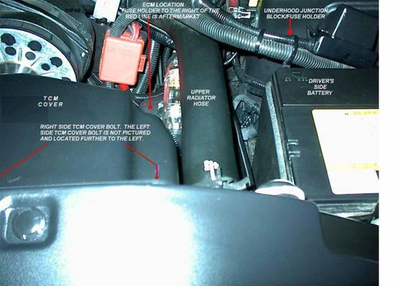
FIGURE 1: ECM and TCM LOCATION (Driver’s side of engine compartment 2001 Duramax Diesel)
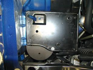
FIGURE 2: TCM LOCATION (Driver’s side of engine compartment 2001 Duramax Diesel)
- The TCM is attached to the radiator shroud by two 10 mm bolts. Removing the TCM allows easier access to the ECM. Remove the two 10 mm bolts along the top edge of the radiator shroud and unplug the (2) connectors from the TCM. The TCM will remain attached to the cover. Lift up and remove the TCM/TCM cover and place them in a safe location to avoid damage. Handle the TCM carefully and avoid dropping it to prevent damage.
- Remove the ECM cover. The black plastic ECM cover comes off by releasing two tabs, one tab near the top edge of the cover located rearward, the second tab is on the front lower edge which is hard to get to (and see). Release the top rearward tab first by reaching between the battery and the radiator hose, and pressing very hard. The front lower tab will then release easily. The ECM plastic cover is a tight fit, but will come out. Release the plastic wire loom clip(s) attached to the cover so the ECM cover can be removed.
- Access to the ECM connectors is made easier by releasing the metal spring latch and the plastic tabs holding the ECM in position.
- You should be able to see the two 80 pin ECM connectors, C1 (blue) and C2 (red). The blue C1 connector faces the passenger side (PS) of the truck and blue may be marked on that side of the ECM. There is a small red area on the top of the DS connector; this is the red C2 connector.
- There is a small bolt in the middle of each ECM connector that holds the connector to the ECM. Remove the bolts from the center of each ECM connector C1 and C2. Unplug the ECM connectors C1 and C2 and remove the ECM from the engine compartment. Handle ECM carefully and avoid dropping it to prevent damage. Place the ECM in a safe location.
- Identify the blue C1 ECM connector. Release the tabs on the wire end of the connector for access to the back of the connector.
- There are small numbers printed on the connector body to identify the terminal positions. Locate terminal position C1-71 and place a small mark on the connector to facilitate identification of this position. C1-71 is the position to add the terminal for the high idle for the Duramax diesel. For reference, terminal position C1-70 should have a BROWN wire in place. Terminal position C1-72 is empty (at least on 2001 models), and C1-73 should have a BROWN/WHITE wire in that position. The colors of the wires referenced for C1-70, C1-72, and C1-73 are from MY2001 and may be different for the MY 2002 – 2003 vehicles.
- Prepare the terminal (GM part #12084913 or #12084912) that will be added to the ECM connector C1-71 by crimping or soldering the terminal to 18 or 20-gauge wire. Using smaller 20-gauge wire will make adding the terminal to the connector easier. If solder is used to attach the terminal to the wire, use sparingly and avoid clumping the solder since it will be difficult to properly seat the terminal in the connector body. Apply a small amount of dielectric grease to the wire terminal. The OEM wire color for this circuit is LIGHT GREEN, but any color wire can be used.
- Using a small pick or other sharp object, puncture the YELLOW insulation from the wire side of the blue C1 ECM connector to correspond to the C1-71 position.
- Remove the translucent plastic cover over the terminal ends of the ECM blue C1 connector by releasing the tabs on each end.
- Insert the terminal you prepared above (with wire attached) from the wire side of the blue C1 connector position C1-71.
- VERY IMPORTANT: Make sure the terminal goes all the way to the edge of the ECM connector to insure proper contact. Use the existing terminals as a guide.
- Replace the translucent plastic cover over the terminal ends and reassemble the cover over the wire end of the blue C1 connector. Carefully inspect the reassembled ECM C1 connector to make sure all terminals are in the proper location.
- Route your added wire as desired toward the firewall. Use split loom tubing, electrical tape, and cable ties as needed for an OEM appearance.
- Reattach the blue C1 and red C2 ECM connectors to their proper location on the ECM. The proper torque valve for the ECM connector bolts is 8 N•M or 70 lb -in. DO NOT OVER TORQUE or damage to the ECM and/or ECM connectors could result.
- Reattach the ECM and TCM to their proper locations. Remember to plug in the (2) TCM connectors, and attach the TCM using the two 10 mm bolts.
- Find a place on the firewall to run the added wire into the cab. On the Duramax diesel, a good location is pictured below:
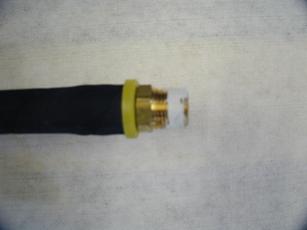
FIGURE 3: FIREWALL ACCESS FOR WIRING (2001 Duramax Diesel)
You can also pierce the rubber boot for the main wire harness entry into the cab located below the hydroboost assembly and run the wires into the cab.
- Find a suitable location in the cab to mount the high idle switch. The metal lip along the bottom of the instrument panel offers a good location to mount a toggle type switch.
- Find a 12V source. A fuse tap can be used to obtain switched 12V power from the fuse panel accessible when the driver front door is opened. It is recommended to use an in-line fuse (1A or 2A) on this 12V power lead as a precaution. If you want to interface the high idle switch with an aftermarket remote start system, you will need to locate an unswitched 12V source for this step. Suggestions for an unswitched 12V power source include direct wiring to the battery, the wiring harness in the steering column, or the fuse panel on the passenger side accessible when the PS front door is open.
- Route the 12V power lead and the high idle wire to your switch location and attach the wires to your switch.
- Double-check all the wiring and connections. Make sure the wires do not interfere with the normal operation of any vehicle components, and will not be pinched or crushed.
- Reattach the battery cables. The ignition switch must be OFF when removing or reattaching the battery cables or damage to the ECM and/or TCM is possible.
HIGH IDLE OPERATION
- Start the truck normally using the ignition key. If using a remote start, the high idle may not work unless a 12V unswitched source was used as the power lead to the high idle switch.
- Set the parking brake. The parking brake MUST be set in manual transmission equipped trucks.
- Transmission should be in PARK or NEUTRAL for Allison equipped trucks.
- Transmission must be in NEUTRAL for the 6 speed manual equipped trucks.
- Vehicle speed must be 0 MPH.
- The brake pedal or clutch pedal is not depressed.
- Turn on the high idle switch.
- Turn on the cruise control switch.
- The idle speed will increase to the STANDBY speed of ~850 RPM for 2001 Duramax diesel equipped trucks. If you have a 2002 or 2003, you MAY NOT see an increase in the idle speed to 850 RPM at this time.
- Hit the cruise control SET button. The idle speed will increase to ~1250 RPM for 2001 – 2003 Duramax equipped trucks.
- Engage the RESUME switch on the cruise control stalk. The idle speed will increase to ~1700 RPM for 2001 – 2003 trucks.
- If the Duramax engine is cold, it may take a few seconds to a few minutes for the high idle to engage. This is normal operation. Some have reported that it may take a few minutes for the high idle to engage when used for the first time.
- Stepping on the brake pedal, clutch pedal, or shifting into gear will turn off the high idle. If the brake pedal or clutch pedal is released, the high idle speed will resume.
- Shifting the Allison back into PARK or NEUTRAL will resume the high idle speed.
!!!!REMEMBER TO TURN OFF THE HIGH IDLE SWITCH BEFORE DRIVING THE VEHICLE SINCE POOR DRIVABILITY CAN RESULT. THIS IS DESCRIBED AS POOR ACCELERATION OR ‘MISSING’ ON ACCELERATION ABOVE ~2200 RPM!!!!