

Duramax Mega Filter Install Overview
Note: The air box, air tube, and inner fender liner are removed to allow access to the mounting area. The key to a successful installation is CLEANLINESS. Be sure all items are clean prior to installing. Hose clamps must be secured VERY tightly. Any leakage will allow air AND dirt into the fuel! Aside from general hand tools, it is suggested that you have a rubber strap wrench, curved tip long nose pliers, and a hand drill with 5/16” or 11/32” bit.
Filter Mounting Base:
Begin by installing the bleeder and filter nipple to the mount. Use a rubber strap wrench to tighten the nipple. Use the supplied oring on the top of the nipple. A dab of pipe thread sealant on the nipple threads is not necessary, but will ensure that it does not back out when the filter is removed.
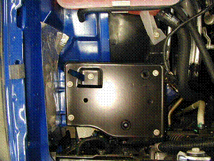
Image #1
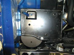
Image #2
The air box is removed to access the tray below. The front outer bolt hole (Image #1) is used to index the mount. Remove the tray and the front outer clip nut from the fender. Drill the hole in the tray for 5/16″ bolt clearance. Drill a second hole 5.25″ center to center from the first hole, and as close to the lip on the tray (Image #2) as you can. I then put the tray on an anvil and pound the lip flat in the immediate vicinity of the hole to allow the flat washer to sit down flat. Bolt the mount to the tray and flip over. To locate the third mounting hole location, insert a scribe or punch through the back side of the hole in the filter mount. Unbolt the mount from tray and drill hole in tray as done for hole #1. Attach the mount to the tray with the supplied 5/16″ bolts/washers in ONLY the two new holes. Assemble only finger tight for now. Install the tray into the truck by slipping the outer fender support (where you removed the clip nut) sheet metal between the tray and the filter mount. Insert the remaining 5/16″ bolt and washer and the original air box tray bolts. Pull tray forward and tighten all bolts securely.
Plumbing the Filter:
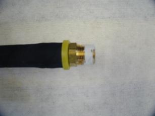
Image #3
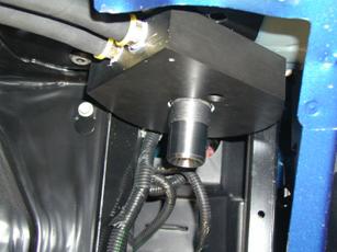
Image #4
Insert a push on fitting (Image #3) into one end of the supplied hose. You will need to use a bit of clean oil and a heat gun or hair dryer to accomplish this. Clamping the fitting in a bench vise also helps. Push completely on until yellow collar no longer rotates freely. Apply pipe thread sealant to the threads of the fitting, and attach the hose to the “OUT” (rearmost) port (Image #4) of the mount. These are pipe threads and will require a significant amount of torque.
Application as a Primary filter:
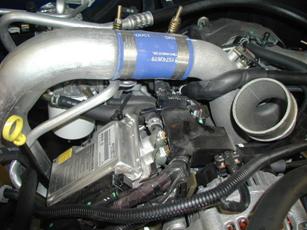
Image #5
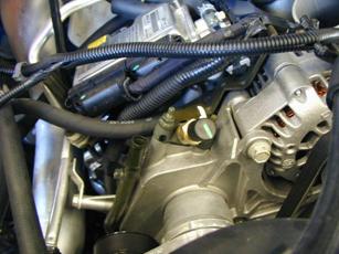
Image #6
Route the “OUT” hose around the EDU on the inboard side (silver box in Image #5) to the “IN” port on the OEM filter. Repeat the fitting insertion and installation to the “IN” port of the Mega mount. This hose will take it’s supply from the short hose that connects the EDU (fuel injection computer) and attach to the banjo fitting at the EDU and return to the inlet of the factory filter at the other end of this hose. Make sure that all hoses are routed free of moving parts and sharp objects. Use the provided hose clamps, and tighten securely.
Application As A Secondary Filter:
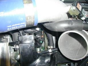
Image #7
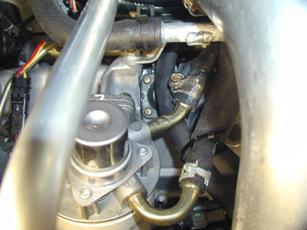
Image #8
Route the “OUT” hose between the EDU and the factory filter unit, the injection pump feed port. (Image #7) Access to the factory spring clamp is VERY limited which is where a 90° curved tip long nose pliers is particularly handy. Cut hose to length, install hose clamp onto hose and push onto fitting. Tighten clamp VERY securely. Repeat the fitting insertion and installation to the “IN” port of the Mega mount. Route the “IN” hose around the EDU (as shown in the Primary installation pictures) to the “OUT” port (Image #8) on the OEM filter. Cut the hose to length and install using the provided hose clamp.
Relocating the horn
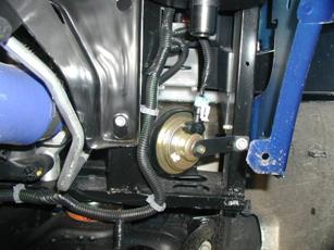
Image #9
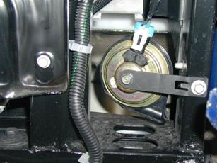
Image #10
he horn (Image #9) will need to be relocated forward. This is done by removing it, and it’s mounting bracket, and then flipping the bracket and reinstalling. (Image #10) The angle of the bend will also need to be lessened. The horn (Image #10) will now be well ahead of the filter and still remain fully functional.
Filter Installation:
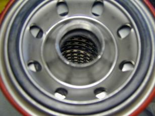
Image #11
Image #12
Apply a thin film of clean oil to the gasket, AND the internal seal, (Image #11) and install onto mount using a strap wrench. Clean the filter body and install the strip of foam weather strip to the body as seen in image #12. This will minimize chafing from the wheel liner. When reinstalled, the inner wheel liner will be slightly displaced by the filter body. Check for tire clearance when using aftermarket wheels and/or oversized tires. Anything under a 265/75/16 should not be a problem.
Bleeding the Mega filter:
As a Primary Filter:
Do not open the bleeder on the Mega filter! Open the bleeder on the OE unit and pump the primer MANY times until fuel comes from the bleeder. Open the bleeder on the Mega filter, and the gravity from the fuel in the hoses will push out any air. Close the bleeder on the Mega filter, and re-bleed the OE filter. Start the truck and idle for a few minutes. It may tend to surge at idle somewhat until all of the air Passes through the system. After the idle has stabilized, you can reopen the bleeder on the Mega filter to allow any additional trapped air to escape. The design of the housing allows it to hold a fairly large volume of air above the suction point, and contains this air holding it near the bleeder. In time, any remaining trapped air will accumulate at this bleeder, so it is a good idea to check and bleed frequently.
As a Secondary Filter:
Open the bleeder on the Mega Filter and pump the primer MANY times until fuel comes out. Close the bleeder on the Mega filter and open the bleeder on the OE filter and bleed here as well. Start the truck and idle for a few minutes. It may tend to surge at idle somewhat until all of the air passes through the system. After the idle has stabilized, you can turn off the engine and pump the factory primer until resistance is felt. Reopen the bleeder on the Mega filter to allow any additional trapped air to escape. The design of the housing allows it to hold a fairly large volume of air above the suction point, and contains this air holding it near the bleeder. In time, any remaining trapped air will accumulate at this bleeder, so it is a good idea to check and bleed frequently.